Force Gauge Test Fixture
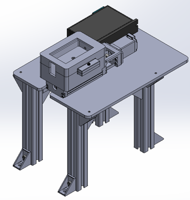
SolidWorks Rendering
This fixture was designed and built to determine the rotational resistance of a theta motion stage. This stage is a new part that will be added to the company’s machine, so this fixture will be used to test multiple new design iterations after I provided measurements on a baseline stage.
Project Summary and Design Steps:
Iteratively designed fixture elements including the base plate and force gauge housing on SolidWorks
Used DFA principles to create an assembly that could mesh with a desired motor, specific force gauge, and separate test bench where the part was mounted
Chose an appropriate linear actuator as the best way to repeatability move the force gauge to the correct measuring point
Made a technical drawing so the base plate could be manufactured and 3D printed the force gauge housing
Assembled the test fixture and secured it to a breadboard with the test bench
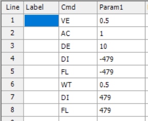
Developed a motor code to enable the actuator to move the right amount of steps to take a force reading of the part through its whole range of motion
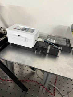
Assembled Test Fixture
Troubleshooting and Results:
Had to create a stopper to ensure that the base of the part being tested did not move when pushed by the force gauge
Also added an extender to the design to enable the fixture to take compression instead of tension readings
Made the fixture fully functional
Ran a set of preliminary tests on a baseline part to provide a reference average force for future tests
Fixture in Motion